Rectifier Circuit Diagram With Explanation
Rectifier circuit precision Rectifier circuits electrical An introduction to rectifier circuits
Solved The following schematic is a rectifier circuit that | Chegg.com
Three-phase rectifier circuit. Practical rectifier circuits Rectifier circuits waveform
Precision rectifier circuit
Rectifier circuit diagram ac dc januaryRectifier circuits dummies signal alternating Rectifier circuit the final output of the rectifier in the form of theRectifier operation.
Rectifier circuit diode single capacitor diagram energy load offering additional signalRectifier and filter circuits schematic circuit diagram Rectifier circuitsWireless charging.

Rectifier circuits and corresponding output signals based on (a), (b) a
Solved the following schematic is a rectifier circuit thatRectifier circuits practical tube ground amp positive Different rectifier circuits and their workingRectifier signals corresponding circuits.
Rectifier circuit circuits articles figure introduction allaboutcircuitsRectifier circuit: what am i doing wrong? Different rectifier circuits and their workingElectrical engineering tutorial: rectifier circuits.

How rectifier circuits work in electronics
Rectifier circuits .
.


Rectifier - Electrical Engineering Centre

RECTIFIER AND FILTER CIRCUITS SCHEMATIC CIRCUIT DIAGRAM

Practical Rectifier Circuits
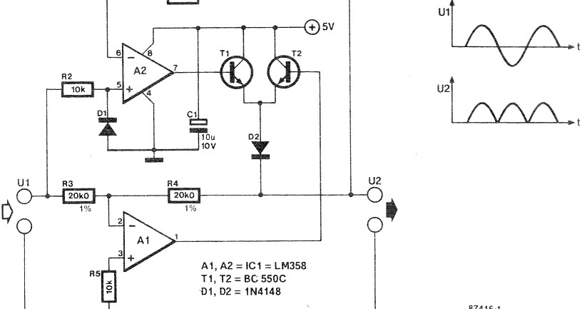
Precision Rectifier Circuit | DIY

Electrical Engineering Tutorial: Rectifier Circuits - YouTube

Different Rectifier Circuits and their Working - Electroinvention

Three-phase rectifier circuit. | Download Scientific Diagram

Rectifier Circuit The final output of the rectifier in the form of the

Solved The following schematic is a rectifier circuit that | Chegg.com
