Push Pull Circuit Diagram
Push pull current driver Push pull circuit converter seekic basic supply power Pull push output pushpull stage circuit cir spice file
dc dc converter - Push pull core saturation - Electrical Engineering
Generic push-pull circuit Amplifier cobra amplifiers Direct_coupled_push_pull
Amplifier push pull class output power wikipedia pushpull operation distortion input read ab electronic electronics classes engineering electrical simplified stack
Designing open loop isolated push-pull converter (part 12/12)Electronic circuit diagram: increasing output push-pull Sg3525 smps schematic pwm circuit mosfet diagram frequency transformer mode kapil complementary generate transformersPush pull amplifier circuit, operation, advantages and disadvantages.
Push-pull output stageDc converter push pull 400v circuit diagram 60w schematics Smps symmetrical diagram converters transformer talema isolation galvanicSchematic of sg3525 based push-pull smps in fig.3 sg3525 pwm controller.

Basic_push_pull_converter_circuit
Push pull circuit400v-60w push-pull dc-dc converter circuit diagram Smps: symmetrical isolated converters : the talema groupPush-pull circuit diagram with cwl525a driven diode.
Push pull circuits balancing self amplifier fig basicCircuit push pull circuitlab description Push-pull amplifiers working,advantages and applications68 info how push pull circuit works with video tutorial.

Push-pull circuit
Circuit push pull diagram seekic driven diode supply power555 push pull output circuit increasing diagram electronic circuits amp Circuit diagram notes converters typicalPush pull circuit amplifier diagram operation disadvantages advantages explanation meter.
Push circuitlabCircuit push pull diagram sg3525 schematic induction using core pwm pulse controller inverter converter dc power topology heating saturation mosfet Self-balancing push-pull circuitsDc dc converter.

Pull push circuit amplifier diagram amplifiers transistor driver gate transistors drive advantages transformer signal input applications working instead use electronics
Push pull converter application notesPush circuit coupled seekic .
.


400V-60W Push-Pull DC-DC Converter Circuit Diagram | Electronic Circuit
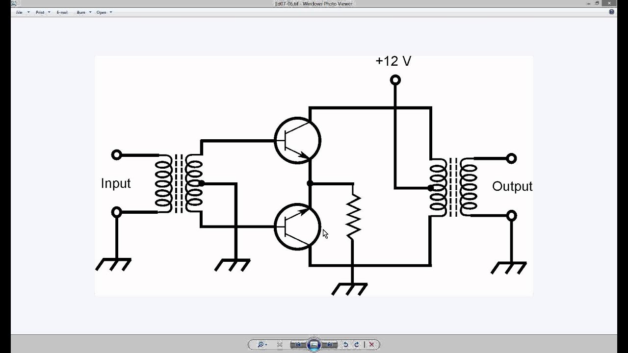
Generic Push-Pull Circuit - YouTube

BASIC_PUSH_PULL_CONVERTER_CIRCUIT - Power_Supply_Circuit - Circuit

Designing Open Loop Isolated Push-Pull Converter (Part 12/12)

Push-Pull Output Stage

Schematic of SG3525 based Push-Pull SMPS In fig.3 SG3525 PWM controller

push-pull Circuit - CircuitLab
electronic circuit diagram: INCREASING OUTPUT PUSH-PULL
